GP/LP 3P600 or 3P606NT user thread

I do wonder tho.....if the individual row units would actually penetrate better for you?.....or are they more a function of that spring pre-load. Dunno. Makes me wonder about finding heavier duty springs. Perhaps from another drill model?

The spring will compress more with more weigh on them = more pre-load.
 
The spring will compress more with more weigh on them = more pre-load.
Then why not simply put more pre-load on those springs? .....by shortening their length (not) or increasing their force (yes). <----in the second case more weight will help......IMO.

I really don't think the spring down-force will be significantly greater by shortening the spring. I believe those are more constant rate springs....and will require a change in force (stronger spring rate) to help in this area. (but I am not positive....lol). We got any engineers in this place?
___________________

Constant-force spring​


From Wikipedia, the free encyclopedia

An ideal constant-force spring is a spring for which the force it exerts over its range of motion is a constant, that is, it does not obey Hooke's law. In reality, "constant-force springs" do not provide a truly constant force and are constructed from materials which do obey Hooke's law. Generally constant-force springs are constructed as a rolled ribbon of spring steel such that the spring is in a rolled up form when relaxed.
As the spring is unrolled, the material coming off the roll (un)bends from the radius of the roll into a straight line between the reel and the load. Because the material tension-stiffness of the straight section is orders of magnitude greater than the bending stiffness of the ribbon, the straight section does not stretch significantly, the restoring force comes primarily from the deformation of the portion of the ribbon near the roll. Because the geometry of that region remains nearly constant as the spring unrolls (with material coming off the roll joining the curved section, and material in the curved section joining the straight section), the resulting force is nearly constant.
_______________

I really got no horse in this race. My drill works good presently. But I do enjoy figuring it out.
 
Last edited:
Riddle me this ..why does the spec sheet say 90 to 180# and why does it say in the manual springs adjustable ? ..
 
I do wonder tho.....if the individual row units would actually penetrate better for you?.....or are they more a function of that spring pre-load. Dunno. Makes me wonder about finding heavier duty springs. Perhaps from another drill model?

The way i figure it, the spring rate only impacts how the weight (down pressure) is distributed amongst the row units when there is variation in elevation or ease of ground penetration.

On a perfectly flat field with completely consistent soil density and no residue to penetrate, spring preload has zero impact. In theory, you could have a solid rod or very soft springs and its still going to have the same down pressure because the weight is distributed evenly amongst the rows when there is no variance row to row in ground condition.

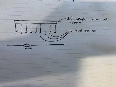
In the very simplified diagram below, when the one row hits that rock, the springs will compress and push up on the tool bar. Doing so will reduce the down pressure (weight) available to all of the other rows. They will all then have less than 133# of down pressure available. If the preload on the spring is 180# vs 90#, the forces that the one row pushes up on the tool bar with are going to be higher (twice as much?) which reduces down pressure available to the other rows by that much more. Say the spring preload was 1200# (for illustration purposes), that one row would eat up all the down pressure available to the entire drill and the only down force on other rows would be the row unit weight hanging to the ground.

Increasing the spring rates might make the openers cut deeper in SOME rows, it does so at the expense of how deep it would cut in others. If the rows units are struggling to get to a certain depth across the width of the drill, the only way to increase down pressure to all of them is to add more weight.

E91711ED-D346-4FAA-9E85-2C21BF04EA1C.jpeg
1EA0B206-0F59-4C46-91EF-D32650ACFE08.jpeg
 
Last edited:
Riddle me this ..why does the spec sheet say 90 to 180# and why does it say in the manual springs adjustable ? ..

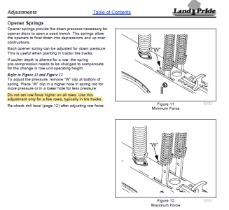
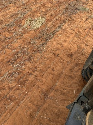
It's so you can get consistent depths when certain rows are consistently in harder to penetrate soil or lower soil, like your tire tracks. It allows those specific rows to have more down pressure but doing so would also reduces the down pressure available to the other rows if on level ground. The manual specifically states not to increase spring pressure on all rows.

1696938988070.png
 
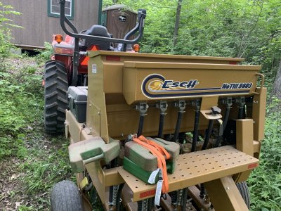
^ Plausible. The thing is....that walkboard is pretty useful for adding seed and cleanup. Kinda hate to clobber that spot up with weight.

I envision them laying flat on the platform, i would just stand on top of them if need be. Obviously not as nice as a clear platform but i'm still nimble enough that I don't think I'd be bothered by it much.

I did this to the esch already to balance it left to right. The weight for the drive wheel on the right side made it run deeper on those rows prior to balancing.
F6A94911-C0F9-4BFE-A84A-1341CEB197DD.jpeg
 
I’m with you Foggy in that my drill has done the job for me but I’m pursuing this to fully grasp the full dynamics of our equipment..
I suppose at the end of the day if machine is level and both drive and Tees are set to minimum and still not satisfactory seed depth.. then weight is needed
 
The way i figure it, the spring rate only impacts how the weight (down pressure) is distributed amongst the row units when there is variation in elevation or ease of ground penetration.

On a perfectly flat field with completely consistent soil density and no residue to penetrate, spring preload has zero impact. In theory, you could have a solid rod or very soft springs and its still going to have the same down pressure because the weight is distributed evenly amongst the rows when there is no variance row to row in ground condition.

In the very simplified diagram below, when the one row hits that rock, the springs will compress and push up on the tool bar. Doing so will reduce the down pressure (weight) available to all of the other rows. They will all then have less than 133# of down pressure available. If the preload on the spring is 180# vs 90#, the forces that the one row pushes up on the tool bar with are going to be higher (twice as much?) which reduces down pressure available to the other rows by that much more. Say the spring preload was 1200# (for illustration purposes), that one row would eat up all the down pressure available to the entire drill and the only down force on other rows would be the row unit weight hanging to the ground.

Increasing the spring rates might make the openers cut deeper in SOME rows, it does so at the expense of how deep it would cut in others. If the rows units are struggling to get to a certain depth across the width of the drill, the only way to increase down pressure to all of them is to add more weight.

View attachment 58238
View attachment 58240
Not so fast here. One thing you fail to depict in your drawing is that center drive wheel which prevents all the weight from getting to the drill openers. (In fact, that wheel could carry MOST of the weight if you have a poorly leveled drill.) Also you pic shows a no till cutter on the drill (like a 606 NT vs a 600 MT) which is comparing apples and oranges. Also, you are disregarding the fact that the individual arms that carry the openers and the packing wheels are hinged in front......so without ANY SPRINGS installed they would only carry the weight of the individual arm......regardless of how much weight you add. I have no idea if those springs are variable rate springs or constant force springs which still may have slight variations when compressed but it is limited. (read the description). I rest my case.......for the moment.
 
It's so you can get consistent depths when certain rows are consistently in harder to penetrate soil or lower soil, like your tire tracks. It allows those specific rows to have more down pressure but doing so would also reduces the down pressure available to the other rows if on level ground. The manual specifically states not to increase spring pressure on all rows.

View attachment 58239
In reality the change in spring "bottom location" is simply being adjusted to compensate for tractor tire depressions.....so that all rows have equal spring compassion starting points. That is why they only offer one position in changing the location. I do not beleive it creates more force.....just a different location to equalize.
 
Not so fast here. One thing you fail to depict in your drawing is that center drive wheel which prevents all the weight from getting to the drill openers. (In fact, that wheel could carry MOST of the weight if you have a poorly leveled drill.) Also you pic shows a no till cutter on the drill (like a 606 NT vs a 600 MT) which is comparing apples and oranges. Also, you are disregarding the fact that the individual arms that carry the openers and the packing wheels are hinged in front......so without ANY SPRINGS installed they would only carry the weight of the individual arm......regardless of how much weight you add. I have no idea if those springs are variable rate springs or constant force springs which still may have slight variations when compressed but it is limited. (read the description). I rest my case.......for the moment.

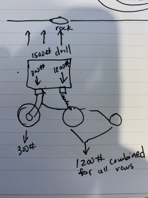
Sir, the front wheel in my excellent illustration is intended to be the drive wheel rather than coulters. The division of weight between them is not at all based on facts, just a wild ass guess used in order to get #'s for discussion purposes.

"without any springs" was meant to illustrate a rigid bar instead of a spring pushing down on the row unit. Of course there needs to be a means to transfer the weight of the drill to the row units.

In reality the change in spring "bottom location" is simply being adjusted to compensate for tractor tire depressions.....so that all rows have equal spring compassion starting points. That is why they only offer one position in changing the location. I do not beleive it creates more force.....just a different location to equalize.
Makes sense for that being the intention. Good point.
 
Last edited:
Note on the above.....if you were to add weights to each individual arm (comprising the opener and closeing wheel assembly) you would better effect the opener penetration......IMO. I did note a location where some barbell weights could be added.....but this may really overload those arms and create undue stresses. Probably not a good plan.
 
Sir, the front wheel in my excellent illustration is intended to be the drive wheel rather than coulters. The division of weight between them is not at all based on facts, just a wild ass guess used in order to get #'s for discussion purposes.

"without any springs" was meant to illustrate a rigid bar instead of a spring pushing down on the row unit. Of course there needs to be a means to push the weight of the drill down to the row units.
My appologies on your art. lol. I forgot who wrote what and I am going too fast. My bad. I can now clearly see that you drew a drive wheel (??).
 
I'm no-where near my drill for a week or more. If I were....I'd take a bathroom scale and place it on a floor jack. Place that combination under ONE pair of openers and take a weight reading. Then begin lifting the scale to see what kind of changes take place. I may be wrong about the constant load springs....but I still maintain that adding allot of weight to the drill will not add allot of weight to each individual row unit. I wish I was wrong on this. (I know I'm stubborn on this.....you can always tell a German....you just can't tell 'em much.)

EDIT: I wonder if the weight variations stated in the manual (from x#/row to y#/row) is the difference in the weight of a fully loaded seed hopper vs an empty hopper? This would pretty much dismiss my contention above.
 
Last edited:
Wind. Move the drive wheel up and try. Also try lowering pressure in the drive wheel. They recommend 60, but no reason you couldn’t run it a bit lower.

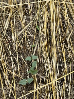
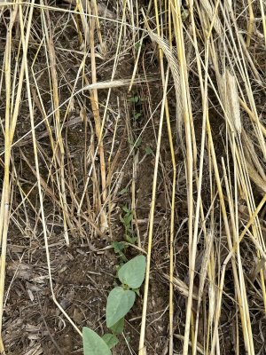
Again, I think wet ground was your main problem. Press wheels just can’t push wet dirt back in (it sticks together). But seed is still in bottom of trench. In drier ground the press wheels will close the furrow imo.

If I move my drive wheel up mine will dig a 2 inch furrow in any type of soil I try. I have cut into dry as a bone hard clay like butter.
 
1696954892246.jpeg
 
I'm no-where near my drill for a week or more. If I were....I'd take a bathroom scale and place it on a floor jack. Place that combination under ONE pair of openers and take a weight reading. Then begin lifting the scale to see what kind of changes take place. I may be wrong about the constant load springs....but I still maintain that adding allot of weight to the drill will not add allot of weight to each individual row unit. I wish I was wrong on this. (I know I'm stubborn on this.....you can always tell a German....you just can't tell 'em much.)

I think you are way overthinking this spring rate thing. The weight of the drill is supported by ground under either the drive wheel or the row units (with contact points @ 9 double disk openers and 9 closing wheels). If I put weight on the walk board on the back of the drill, it aint all getting transferred to the drive wheel at the opposite end of the drill.

In my lone run thus far, there wasn't even any weight supported by the closing wheels at times because the the openers didn't penetrate the ground enough for the closing wheels to be firmly on the ground. So additional weight would absolutely go into the openers, especially since the closing wheels generally only support weight once the opener for that row is to the desired depth.
 
Last edited:
I think you are way overthinking this spring rate thing. The weight of the drill is supported by ground under either the drive wheel or the row units (with contact points @ 9 double disk openers and 9 closing wheels). If I put weight on the walk board on the back of the drill, it aint all getting transferred to the drive wheel at the opposite end of the drill.

In my lone run thus far, there wasn't even any weight supported by the closing wheels at times because the the openers didn't penetrate the ground enough for the closing wheels to be firmly on the ground. So additional weight would absolutely go into the openers, especially since the closing wheels generally only support weight once the opener for that row is to the desired depth.
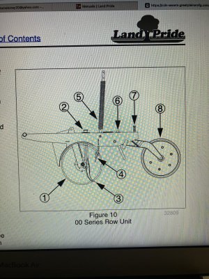
You may be right here. But look at the illustration of the drill on page 21 in the manual. On the far left is a hinge point, and the only way to get more down pressure on that row is thru that spring. Maybe those springs are variable rate springs? (increasing pressure as they are compressed) Dunno. The press wheels just limit the amount of downward (trench depth) travel of that row and perform closing duties.


tempImageqB1ZWW.jpg
 
You may be right here. But look at the illustration of the drill on page 21 in the manual. On the far left is a hinge point, and the only way to get more down pressure on that row is thru that spring. Maybe those springs are variable rate springs? (increasing pressure as they are compressed) Dunno. The press wheels just limit the amount of downward (trench depth) travel of that row and perform closing duties.


View attachment 58261

I'm not following this constant vs variable rate spring talk. If you took that spring as a stand alone part, stood it up on a scale, then put 100# on the top end so it compressed the spring, the weight (down pressure) is going to be 100# + the weight of the spring. If you put 200# on top of the spring, the weight is going to be 200# + the weight of the spring, regardless of how much the spring is compressed.

The preload value really just impacts how the loads are distributed from the drill tool bar to each row unit when there is not consistent ground conditions and elevations across the width of the drill.
 
Last edited:
I'm not following this constant vs variable rate spring talk. If you took that spring as a stand alone part, stood it up on a scale, then put 100# on the top end so it compressed the spring, the weight (down pressure) is going to be 100# + the weight of the spring. If you put 200# on top of the spring, the weight is going to be 200# + the weight of the spring, regardless of how much the spring is compressed.

The preload value really just impacts how the loads are distributed from the drill tool bar to each row unit when there is not consistent ground conditions and elevations across the width of the drill.
Well.....I learned another angle today. FWIW....
linear-versus-progressive-springs


Here is the important part:
When we talk about variable rates and constant rates, we are referring to the rate of force acting upon the spring, or “deflection.” Constant-rate springs have a uniform rate of deflection because they are the same diameter from top to bottom. So, for example, a spring with a 200 pound-per-inch linear rate will compress one inch for every 200 pounds of load that is applied. This is true for the entire length of the spring, so after 600 pounds of load, for example, the spring will have compressed three inches.
 
Top