Stump shredder project

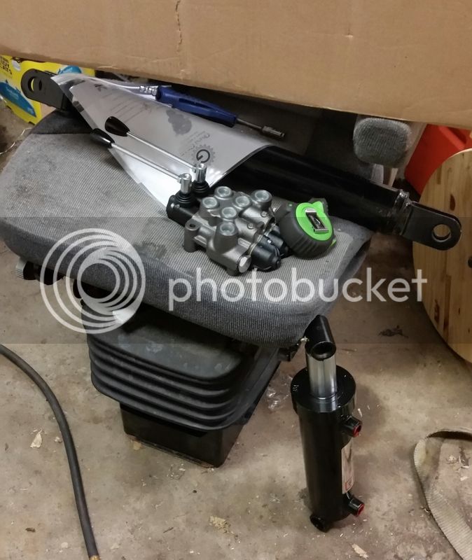
After much cogitating, and getting down to flow capacity and dual demands on the low flow tractor pump, then looking at the additional crap needed to run another pump off the PTO, I decided that Foggy's right and the hydraulic front mount shredder is a no-go.

So Sunday I dropped a wad on Surplus Center and got a 83hp rotary cutter gearbox after confirming with Omni's engineer that the vent just needed to be plugged for use in the horizontal position - and that stuff showed up Wed.

20150814_024632.jpg


20150814_024645-1.jpg


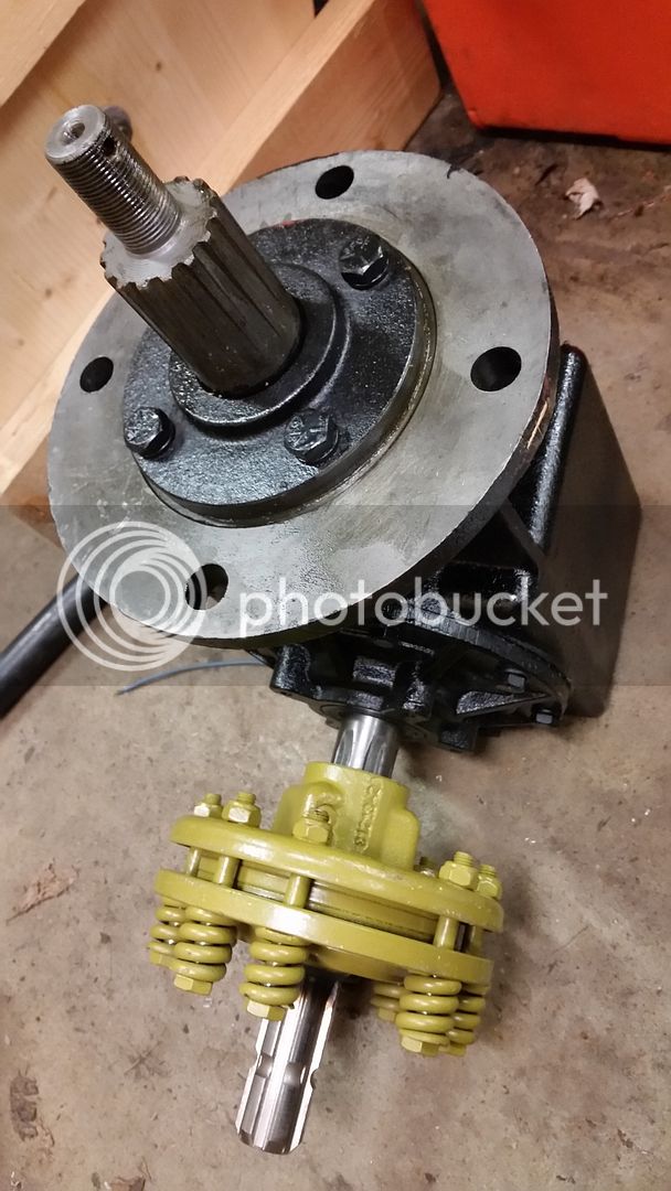
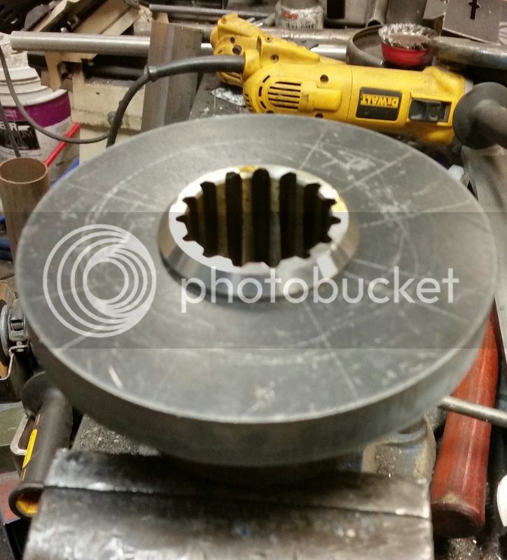
Yesterday I started working on the hub for the gear box:

20150814_011503-1.jpg


20150814_013932-1.jpg


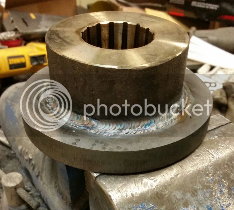
Then did a triple pass weld on the back (to limit heat input given the splines) and zipped up the front:

20150814_024421-1.jpg


20150814_023452-1.jpg


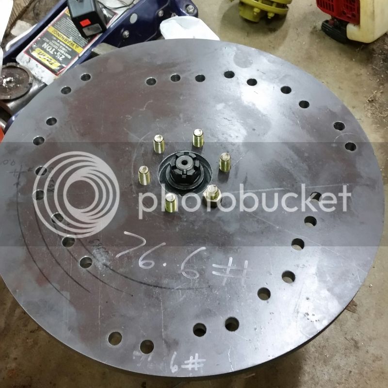
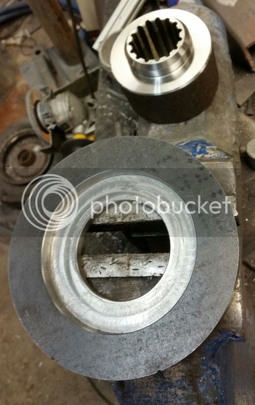
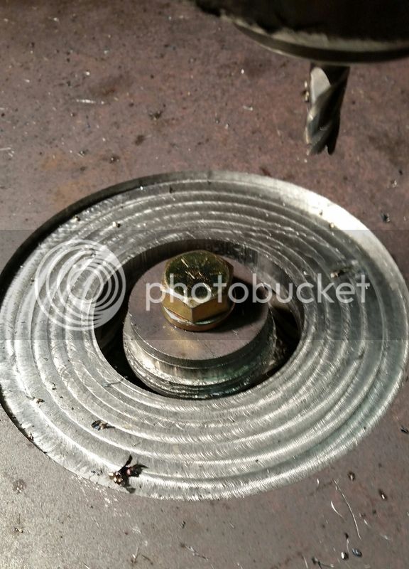
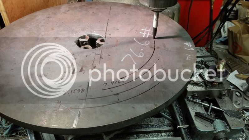
Today I got more materials for the 3pt side of things, and trued up the flange on the hub, and then cut the mating surface on the wheel:

20150814_195535-1.jpg


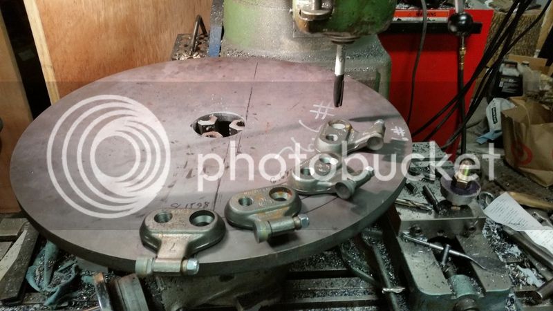
Used my super high-tech GreyMatterCAD system to test my layout theory:

20150814_233122.jpg


20150814_233526.jpg


Then did some math and drilled a bunch of holes:

20150815_024644.jpg


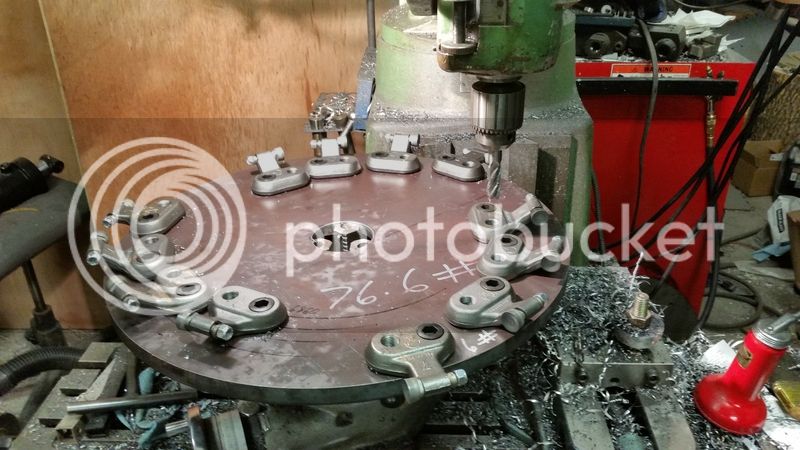
I should've moved the inner most cutter over a couple more degrees, but they fit fine.

My right hand started spasming while I was doing the last 3 holes for the pockets. I finished those out despite it probably not being the best idea to keep going. Then stopped for the night, short the 6 mounting bolt holes for the hub flange and a clean up pass to true up the disk. Oh well, I'm pretty satisfied with where I am.


And Foggy, if you get a chance, could you measure the frame to gearbox input shaft length on your grinder for me? I'm not positive on that dimension for mine yet.
 
Looking great!!!!

Your pics are bringing back lots of great memories (I was a machinist at one pt in life).
 
Thanks CS!

Working the wheel has been a lot easier than I thought since it's so stiff. I had planned on needing to support the edge given the distance from center I'd be drilling but it just sits there and takes it. Minimal chatter even when boring with the 5/8" end mill through a 3/8" pilot.
 
Thanks CS!

Working the wheel has been a lot easier than I thought since it's so stiff. I had planned on needing to support the edge given the distance from center I'd be drilling but it just sits there and takes it. Minimal chatter even when boring with the 5/8" end mill through a 3/8" pilot.

The amount of ingenuity and mechanical/technical ability that you have is incredible. I'm by no means mechanically inclined, but I can usually figure out how stuff works. THIS is a whole different level than I can even comprehend!
 
And Foggy, if you get a chance, could you measure the frame to gearbox input shaft length on your grinder for me? I'm not positive on that dimension for mine yet.

^ Nice work Jim. Not sure what dimension you are looking for here?? I may get over to my land later in the week......and could get a measurement for you......but I need a diagram or something.....cause I am confused. o_O
 
Thanks guys!

maxresdefault.jpg


I'm guessing it's around 24", since that would place the pivot at the halfway point for happy u-joints in the drive shaft.
 
OK....will see if I can get some numbers for you soon. (I'd guess it to be from 24 to 32 inches??)
 
Do you remember off hand how long your driveshaft is?
 
Pretty light day today to let the nerves settle.

Got the wheel done (added another hole to move the inner cutter over), and the hub drilled. Still needs a little finesse to get the bolts to sit right, but she's getting there.

20150816_011851-1.jpg
 
^ you got spare holes? ;) I do not remember the length of my PTO shaft....but will report on it later today with the other info.

Glad you changed your mind on a loader mounted unit......I think you would have been very hard on those loader joints. I think my stump grinder is what led to breaking one of my three point lift arms. I get pretty aggressive at times when operating my grinder. :D

Good looking project. Gotta give you credit.....you do take on some tough ones.
 
Jim. Here are the measurements I took on my stump grinder:

From end of input shaft on the slip clutch to U Shape frame is 28"

My Pto Shaft when measured closed with the Ends is : 47" total. The tube(s) are 48" long, so the shaft must telescope about 48".
 
^ you got spare holes? ;) :D[/QUOTE]

Yep, I moved the inner most pockets over one length to space them a little better.

Thanks for the measurements! That confirms my own calculations for mine.
 
Where did you get that cutter placement? Seems odd to me. o_O
 
Look at Greenteeth's site and you'll see something very similar - however, I came up with mine based on a roughing endmill's tooth placement.
 
3pt frame is coming along nicely.

20150819_004352-1.jpg
 
Any extra weight you can add to the grinder would pay a dividend IMO. Also any spikes into the ground at this frame would serve to make things rigid and avoid chatter. You want this frame to stay glued to the ground as you sweep the cutter head.
 
Extra weight is why I'm using the I-beam, that and I had it. :) I have another section of this size beam that'll fit between the channel legs I might scab on to the back (tractor side) to add more weight yet.

I don't know that spikes would do much. If they're driven in by the weight of the implement, then they're only going to hold as much as what's above them is pushing them down, and that's the same mass that's got to be overcome to lift them out when the cutter pushes. Power down force would be the real solution, but my tractor doesn't have it.

Weight is the key to smooth cutting on any milling machine, so this grinder will be one heavy sucker!
 
Correct me if I'm wrong, but spikes should help counteract the lateral forces of your spinning blade. Even with minimal wt on a t-post, it still doesn't move sided to side very well when you push on them. Even if they don't go far into the ground I would think spikes would stabilize things quite a bit when those blades are hammering into a stump.
 
It'll be attached to a 7,000# dead weight. The only problem is that the 3pt mechanism isn't designed to counteract vertical forces, and that's exactly what you create when spitting chips away from the tractor. Without power down pressure, the spike's only engagement is the weight perched above it. The cutter already has to overcome that to bounce the chassis, so you gain nothing.

I'm going to add a leg to the left side (right side of tractor) to add stability to twisting forces from the cutter head. Some of the designs that are made for bigger tractors have the swing pivot in the center to accomplish the same thing. I decided I wanted to do something different that made following suit impractical, so I'll be making my base wider yet.
 
Gotcha, Hate to say it but I was envisioning a horizontal blade and not a vertical when I wrote that. After I scrolled up the page (and saw a picture) I realized I had it all wrong.

Once again, I'm loving the build and ingenuity going into it. You make me wish I still had access to a machine shop and equipment!
 
Top