yoderjac
5 year old buck +
I know Bill uses BEC and John has been asking questions on other threads. I thought I'd start a thread showing an example of the evolution of a network. Everything here is using the older BEC Orion cameras. They have higher powered radios than the newer X7D and X80 series so distances may be different, but the principles all apply to those newer cameras as well.
Here is an actual example of how a network is established and evolves over time. I started by doing a signal survey. I started with the stock antennas on the PC base and one camera. I drove around on the ATV and tested the signal levels at different locations with the camera. From this I determined I needed higher power antennas and enough height to minimize attenuation from our pines.
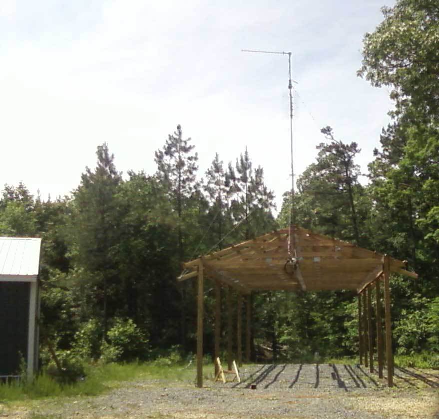
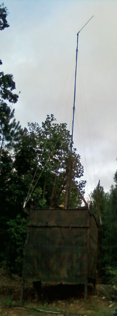
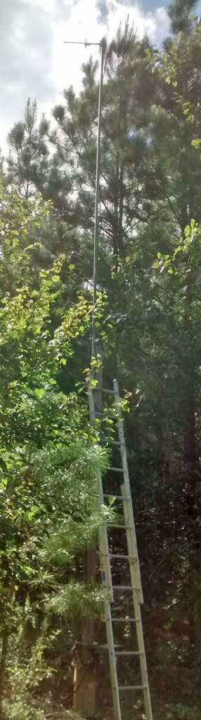
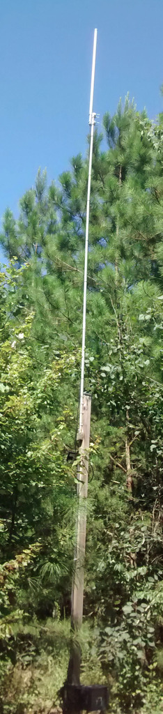
I decided to build a pavilion to park my trailer under and I used that structure to support an antenna mast with a 13db yagi with a rotor on the mast. This allows me to adjust how where the yagi is pointing if I decided to move cameras.
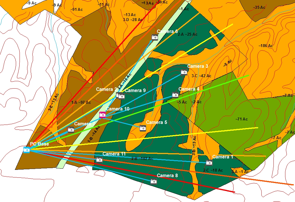
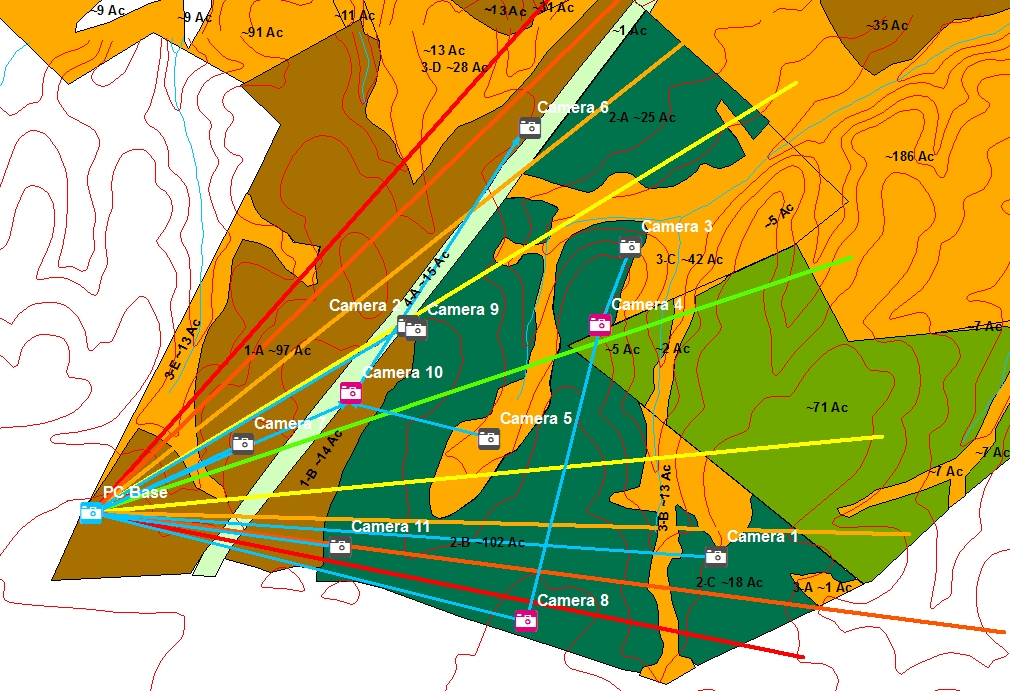
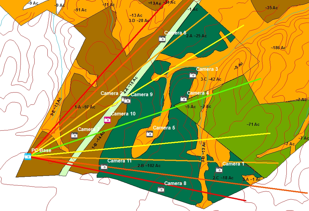
The next picture is a map that shows my camera placement, and topography.
A yagi antenna move energy from one side in the horizontal direction to the other (as well as vertical). The PC base is at the SW corner of our property. The picture shows the highest power of the antenna as the dark green wedge. The light green is slightly lower power, then yellow, orange and finally red shows the lowest usable improved gain. If the antenna was 9 db instead of 13, the areas of high power would be less sharp and wider. By the way, this graphic is a bit over simplified and not actually an antenna pattern, but is instructional from a practical level.
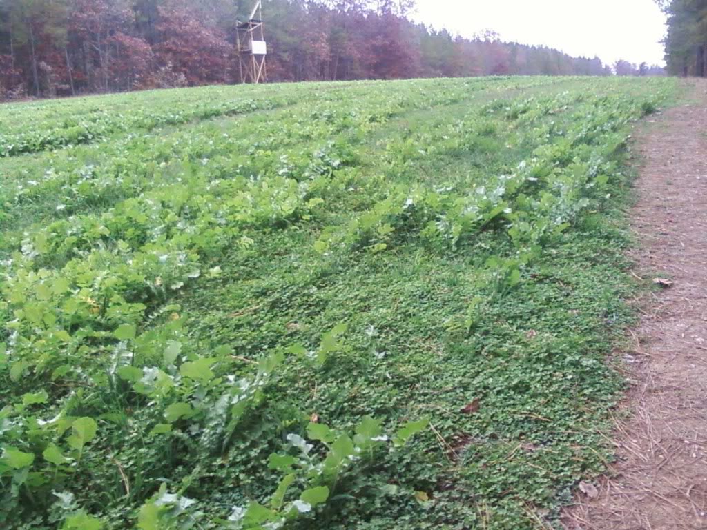
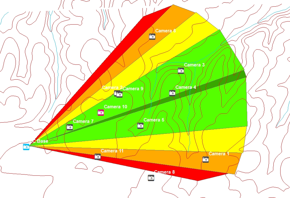
So the first consideration was topography because ground provides total blockage compared to vegetation which will attenuate the signal. The next consideration was vegetation.
This picture shows land use. I've replace the solid wedges representing the antenna pattern with lines only so you can see the land use. The orange-ish yellow represents our hardwood riparian buffers and ridges. The brown area represents more mature pines. The dark green represents young pines and the light green is an age class of pines in between the other two. The pale green is a open pipeline.
Continued...
Here is an actual example of how a network is established and evolves over time. I started by doing a signal survey. I started with the stock antennas on the PC base and one camera. I drove around on the ATV and tested the signal levels at different locations with the camera. From this I determined I needed higher power antennas and enough height to minimize attenuation from our pines.
I decided to build a pavilion to park my trailer under and I used that structure to support an antenna mast with a 13db yagi with a rotor on the mast. This allows me to adjust how where the yagi is pointing if I decided to move cameras.
The next picture is a map that shows my camera placement, and topography.
A yagi antenna move energy from one side in the horizontal direction to the other (as well as vertical). The PC base is at the SW corner of our property. The picture shows the highest power of the antenna as the dark green wedge. The light green is slightly lower power, then yellow, orange and finally red shows the lowest usable improved gain. If the antenna was 9 db instead of 13, the areas of high power would be less sharp and wider. By the way, this graphic is a bit over simplified and not actually an antenna pattern, but is instructional from a practical level.
So the first consideration was topography because ground provides total blockage compared to vegetation which will attenuate the signal. The next consideration was vegetation.
This picture shows land use. I've replace the solid wedges representing the antenna pattern with lines only so you can see the land use. The orange-ish yellow represents our hardwood riparian buffers and ridges. The brown area represents more mature pines. The dark green represents young pines and the light green is an age class of pines in between the other two. The pale green is a open pipeline.
Continued...
Last edited: